BOEING 727 HYDRAULIC SYSTEM
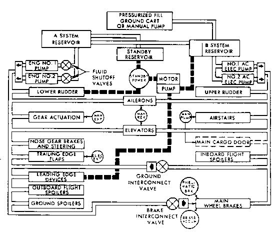
(Below) B-727 Hydraulic Power Systems.

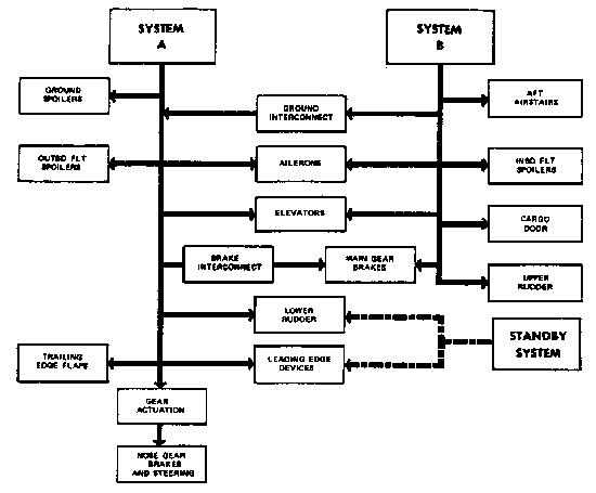
(Below) B-727 Hydraulic System A and System B Interconnections.

The Boeing 727 has three hydraulic systems -- System A, System B, and a Standby System. During flight, both Systems A and B are normally on at all times. The Standby System is normally off during flight unless needed. Standby hydraulics power the lower rudder and leading edge devices. All three systems have a nominal pressure of 3,000 PSI. Systems A and B have a pressure relief valve which is automatically activated at about 3,500 PSI.
System A pumps are engine-driven (inoperative until engines 1 and/or 2 are started). System B is driven by electrical pumps and can be used whenever AC electrical power is available. The Standby system is also driven by an electrical pump and is activated by either turning off System A pressure to the lower rudder or by turning the Alternate Flaps Master Switch on.
Hydraulic Accumulator...
Hydraulic accumulators absorb surges in hydraulic pressure and are incorporated into both Systems A and B. The accumulator uses a 1,000 PSI air precharge. Should hydraulic pressure exceed the precharge, the accumulator pressure will equalize the system pressure. (With a hydraulic system depressurized, accumulator pressure should be 1,000 PSI.) Loss of precharge pressure will result in inaccurately low hydraulic pressure indications.
System A and System B Interconnections...
Although Systems A and B are independent of each other, there are interconnections between the two.
A balance line runs between System A and B hydraulic reservoirs. The System B reservoir will always be full if the System A reservoir quantity is more than 2.5 gallons. Such an arrangement allows both reservoirs to be serviced from a single point. (The Standby reservoir is also filled from the System A tank.) Should fluid quantity fall below 2.5 gallons, System A will be completely independent of System B. Hydraulic leaks in System B would be initially indicated by decreasing hydraulic pressure in System A.
The ground interconnect valve allows System B fluid to pressurize System A for check out when no engines are running. (A source of AC power must be available to power System B.)
The brake interconnect valve allows System A pressure to be applied to main wheel brakes in flight or on the ground. This provides a "backup" source of hydraulic pressure for brakes. Nothing else in System B can be supplied with System A pressure.
Fluid for System A and System B is cooled in heat exchangers in the Number 3 and Number 1 fuel tanks respectively.
System A...
The System A reservoir is pressurized by 13th stage bleed air from engines 1 and 2 which drive the System A pumps.
System A pump switches don't literally turn the hydraulic pumps off. Instead, whenever a pump is turned off, a solenoid blocks the pump output and depressurizes the pump. Hydraulic fluid still cycles through the pump to both cool and lubricate it. Pump switches should be left in the on position when the aircraft is shut down.
System B...
Recall that the System B pumps are electrically driven. They deliver fluid at a constant pressure of 3,000 PSI. The flow rate depends on system demand.
When System B pump switches are turned off, the electric motor stops and all pump output ceases. System B pump switches should be turned off when the aircraft is shut down to prolong the life of the electric motors.
Standby System...
Should System A become inoperative, the Standby system (pressure supplied by electrical pump) supplies hydraulic pressure to operate both the leading edge [wing] devices and the lower rudder. Alternate flap switches allow the trailing edge flaps to be operated electrically. Once down, the leading edge devices are held in place by mechanical locks and cannot be retracted using "Alternate Flaps" controls. (Trailing edge flaps which are normally on System A may be retracted via the electrical motors.)
Hydraulic Notes...
Because of the hazard to personnel from control surfaces, doors, etc., ground clearance should always be received prior to powering any hydraulic system.
The aircraft is towed by its nosewheel. If the torsion links which connect the nosewheel to the steering mechanism are connected, the System A pumps should be depressurized. This will prevent actuation of nosewheel steering with a tow bar connected.