
BOEING 727 JT8D ENGINE SYSTEMS
The JT8D Engine...
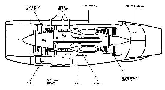
The engine has three sections: the compressor section, the burner section, and the turbine section. Air enters the compressor section and passes through a series of rotating and stationary airfoils. This raises the pressure and temperature of the air. (In the case of the B-727, a pressure increase of 15:1 and temperature increase of 700 F.)
The JT8D engine used on the 727 is a "twin spool" type engine. There are two independently rotating sets of compressors and turbines. The forward 6 stages of compressor blades (N1) are driven by the aft 3 stages of turbine blades through a connecting shaft. Compressor stages 7 through 13 (N2) are connected to their respective turbine via a concentric shaft.
As the air exits the compressor section, it enters the burner section where air and fuel are mixed together. Once ignited, the mixture of fuel and air maintains a continuous combustion cycle without further need of ignition sources. The burning fuel causes a large increase in air volume and since there is a higher pressure in the compressor section, the air exhausts through the turbine section.
The turbines, in turn, drives the compressors. As the turbines take energy from the air, there is a drop in both temperature and pressure.
At takeoff thrust there is roughly a 2:1 ratio between the air pressure entering the engine and the air exiting the engine through the tailpipe.
In the JT8D, some air coming from the first 2 stages of the compressor (fan stage) bypasses the rest of the compressor, burner, and turbine sections. This "bypass" air is then mixed with the jet exhaust at the tailpipe. This improves takeoff performance and provides some cooling.
There are two sources of accessory power from the engine: N2 Accessory Drive and Bleed Air.
The N2 Accessory Drive is a mechanical drive which connects the N2 rotor to a gearbox under the engine. This gearbox drives items such as electrical generators, fuel and oil pumps, and hydraulic pumps.
Bleed Air from the various stages of the compressor is used for pressurization, anti-icing, engine starting, and air conditioning.
Engine Pressure Ratio (EPR)...
Thrust is measured in EPR (pronounced "eeper"). EPR is the ratio of turbine discharge total pressure to compressor inlet total pressure. For example, an EPR of 2.0 means that the pressure at the turbine discharge is 2.0 times as great as the pressure at the compressor inlet.
Engine Fuel System...
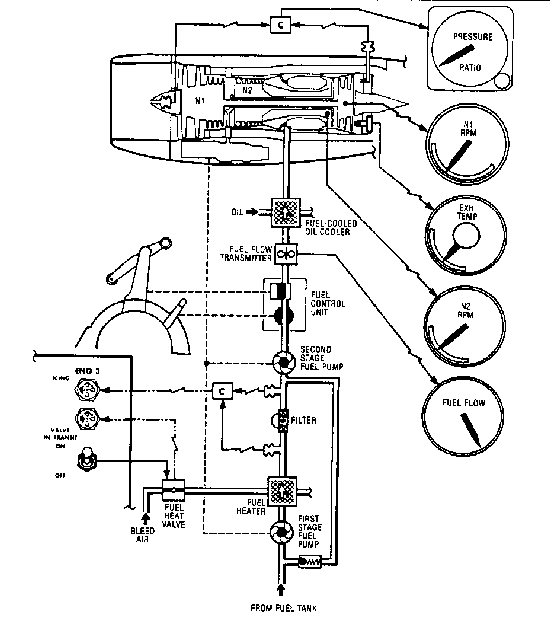
The fuel goes through 2 stages of an engine driven fuel pump. These pumps are driven by the N2 Accessory Drive.
After the fuel passes through the first stage fuel pump it goes through a fuel heater followed by an associating fuel filter. If there is reduced fuel flow through this filter (by ice or any foreign debris) an amber ICING light is illuminated on the flight engineer's panel.
Any time an ICING light is on, fuel heat should be applied to all engines. Fuel heat takes allows 13th stage bleed air (as hot as 750 F) to enter the fuel filter. Heat should be applied for 1 minute, then for one minute every 30 minutes should the light remain on. Application of fuel heat will cause an increase in oil temperature as the oil is fuel cooled. Any change in fuel temperature will result in an almost immediate change in oil temperature. If fuel heat is applied and the light does not extinguish, this is an indication that foreign debris other than ice are clogging the fuel filter.
With one stage of the pump failed, the engine will probably run but will be unable to produce takeoff power. Should both stages fail, the engine will flameout from fuel starvation.
Fuel heat should be applied for one minute prior to takeoff or landing if the fuel temperature is 0 C or less, but should not be used during takeoff or landing and should not be used with high oil temperatures.
Fuel is metered to the engine via a device called a Fuel Control Unit. Items which affect its operation are:
As fuel both cools and lubricates the engine driven pumps, if an engine is shut down in flight, fuel flow should be restored for 3 minutes each 30 minutes. This prevents damage to the pumps and fuel control unit.
Engine Oil System...
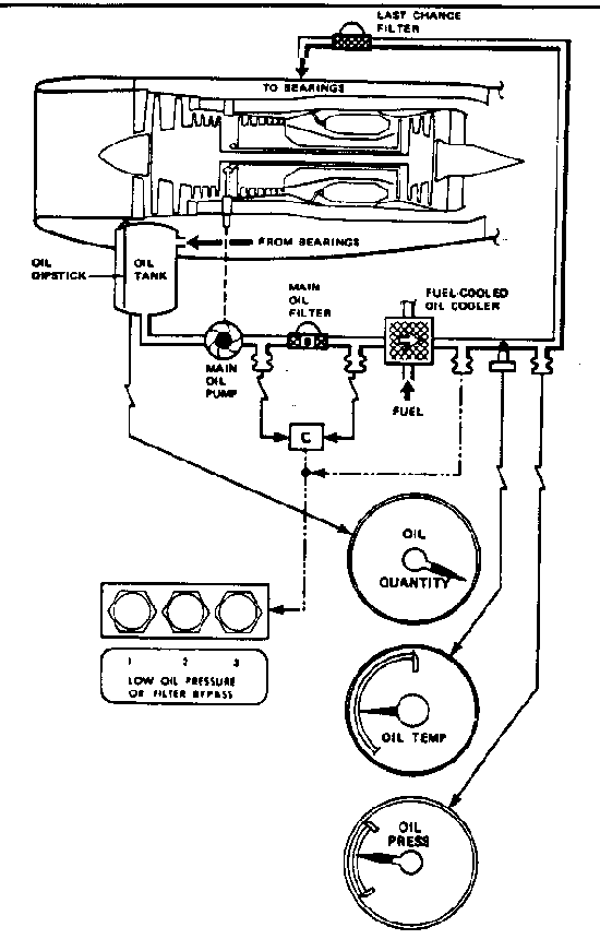
Oil quantity (indicated on the engineer's panel) indicates the amount of usable oil in the oil tank. On the JT8D engine, it is common for the oil quantity indication to decrease after engine shutdown.
Oil drains from the tank into the engine. Upon engine start that oil is returned to the tank which shows an increase in oil quantity Should the oil quantity indication decrease after engine start, there is a leak in the oil return line and the affected engine should be shutdown immediately.
A light on the pilot's center peal will illuminate if oil pressure becomes too low or if the main oil filter is clogged and being bypassed.
If an oil filter bypass is open, the first action is to reduce the power in an attempt to reset the filter. If the light remains on, the engine must be shutdown.
Oil pressure limits for the 727 are:
NORMAL RANGE: 40 to 55 PSI
CAUTION RANGE: 35 to 40 PSI (acceptable at idle power only)
Remember, oil temperature will increase if fuel temperature increases and/or if fuel flow is reduced.
Engine Start System...
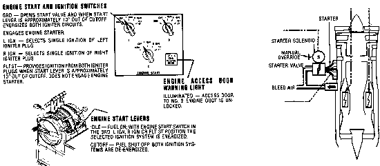
To start the 727's engines, you need both low pressure bleed air (minimum pressure 30 PSI) and a source of D.C. electrical power. Electrical power can be supplied by the APU, external source, an aircraft generator, or by the battery. The low pressure bleed air can come from the APU, an external source, or from a running engine.
The start sequence involves two sets of controls:
When the start switch is placed in the GROUND START position, the starter solenoid causes the valve to be pneumatically opened and bleed air drives the starter. The air turbine starter is geared to the N2 compressor. The rotation of the starter in turn rotates the N2 compressor which draws starting air into the engine. Ignition is not activated by the start switch but it is armed. Should the start switch be inadvertently released, wait until N2 reaches zero RPM before re-engaging.
At about 15% N2 RPM and with N1 RPM, the start lever should be moved from CUTOFF to IDLE. This allows the fuel to flow through the fuel control unit and also activates high energy igniters in two of the burner cans.
There should be an indication of fuel flow as soon as the start lever is moved from CUTOFF, followed shortly thereafter by a rise in Exhaust Gas Temperature (EGT) indicating that the engine is "lit." The engine will then accelerate toward idle RPM. At 36% to 39% N2 RPM, the starter valve will automatically close, the indication of which is a rapid rise in duct pressure which can be observed on the flight engineer's panel.
If there is no increase in duct pressure by the time 40% N2 is reached, a starter overspeed has occurred. In this instance, bleed air must be closed off and the engine shut down. The starter will have to be replaced before the engine can be run.
A starter valve may stick closed in low temperatures due to ice freezing the solenoid. In this case, the start switch may be held in the GROUND START position as long as necessary to melt the ice and activate the starter.
"Hot starts" are malfunctions where EGT rapidly rises above starting limits. This can cause serious damage to the engine. A fuel flow in excess of 1,500 lbs per hour during the start cycle will almost always result in excessive EGT indications...a shut down being necessary.
The correct procedure to follow for an aborted start is first place the start lever in CUTOFF. This will show off fuel and deactivate the igniters. The start switch should be held in GROUND START for 15 seconds to cool the engine and, more importantly, purge the engine of excess fuel by blowing it out the tailpipe.
If an engine is to be shut down in flight, slow the RPM to stabilize at idle for 2 minutes prior to shutdown, if possible.
To restart in flight, an "air start" may be attempted. The start switch should be placed in the FLIGHT START position which will arm high energy ignition. The starter valve will not open. Ram air entering the engine is sufficient for start if the aircraft's speed is above 150 knots. When the start lever is moved to IDLE, fuel is introduced and the igniters are activated.
Reverse Thrust...
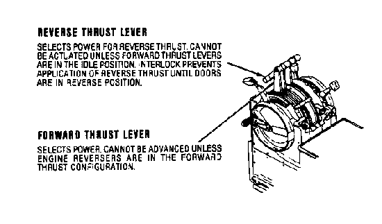
The reverse thrust system uses clamshell-type doors on each engine to deflect exhaust gases in a forward direction. The 727's reverse thrust system is not designed to be used in flight. It can be used to back the aircraft, but great caution should be used at speeds of less than 70 knots because of possible exhaust gas ingestion and engine damage.
It is highly unlikely that a reverse thrust door could unlock in flight and develop reverse thrust. If a REVERSER OPERATING light illuminates in flight, the thrust lever should be retracted to idle. If the thrust lever will advance freely from the idle position, the door is not deployed and the engine can be operated normally. If the forward thrust lever cannot be advanced, the interlock is engaged which indicates that the deflector doors are not stowed. If this is the case, shut down the engine and land at the nearest suitable airport.